top of page

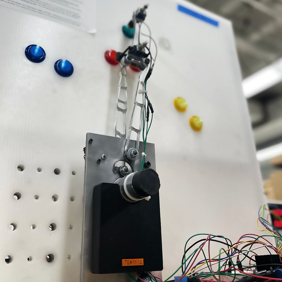
The goal of the project is to design, build, and control a complex linkage mechanism to press arcade buttons in sequence as quickly as possible. The machine uses a DC electronic motor in a closed-loop position control system that moves the button-pressing mechanism to the desired position and orientation accurately enough to press the buttons, and quickly enough to press as many as possible.
Team Lead
Managed team throughout the duration of the project. Coordinated weekly meetings and ensured assignments were delivered on time.
Timeframe
16 weeks
Software
SolidWorks
Arduino
Design & Manufacturing
Designed all the components of the machine, including the button-pressing mechanism, created assemblies and renderings, machined linkages and spacers, and soldered electronic components.
Wiring, Assembly, & Testing
Wired all the electronic components, assembled linkage, and tested motor, limit switches, and solenoids before proceeding to the implementation of the state machine.
Team Members
Ryan Wu
Nicholas He
Manufacturing
Tormach Mill
Tormach Lathe
Drill Press
3D Printers
Laser Cutter
Arbor Press
Waterjet
Soldering Iron
Transmission Angles of Four-Bar-Linkage
Sketched multiple pivot positions on SolidWorks to decide on the most ideal angles between the coupler and output link for
three different positions.
As shown in the image to the right, the three transmission angles are:
-
Position 1: 104.9
-
Position 2: 82.39
-
Position 3: 84.11
.png)
Coupler Design
The following criteria were taken into account when designing the coupler:
-
It must hold two solenoids that are able to press the red or green buttons in the same position.
-
It has to follow transmission angles and playing field layout.
-
It has to be designed for manufacturing (using either a waterjet or milling machine).
.png)
Linkage Design
The following criteria were taken into account when designing the linkage:
-
The links must meet established transmission angles.
-
They have to be designed for manufacturing (using a waterjet).
Links were optimized on SolidWorks. FEA simulations were conducted to validate the design and optimizations.
Assembly
After the ground plate, button-pressing mechanism, brackets, and spacers were designed, an assembly was created with hardware components included.
.png)
Transmission Ratio
-
The transmission ratio was selected based on inertia matching as well as checking against the encoder resolution limit.
-
After finding the masses and moment of inertia of all of the linkages (including the bolted connections to the coupler), the distances between the joint positions and instant centers are found to determine the total inertia after parallel axis transformation.
-
Since the z-axis CG of the coupler did not lie between the pivots, the R5 distance accounted for the additional distance beyond the pivot centerline.
-
Matching this against the 25000 g/cm^2 inertia of the motor leads to a transmission ratio of 2.078.
Transmission Components
-
1045 Carbon Steel Pinion Gear (driving)
-
Brass Gear (driven)


The limit switches, toggle switch, encoder, and motor driver were tested. The button-pressing mechanism was calibrated before starting to tune the PID controller. The state machine was implemented and refined for optimal results.
The mechanism scored over 200 points in one minute!
bottom of page